Friday 15 December 2017

Bio-Signal based Home automation using Arduino and Raspberry Pi


So... I've been working on this project with my friends for a year. It was for a contest(And we won. fuck yeah.)
Now since that shit's over, I thought that I should document it. So here it is.

So, Here's The Deal.

people sleep, right? And sometimes, when you're watching Netflix, or just normal TV, or just...whatever, you fall asleep with appliances on.  Then those appliances use electricity. That's bad. For the environment, and for yer bills. So, what if there was a device that turned off appliances when you fall asleep? and turn the lights back on when you're awake? I mean, you gotta get up to turn the lights on. If you have bad eyesight, or you're old and can't see well in the dark, your house can be a fucking hazard. If the light turn on automatically when you're awake, that would be awesome. So, me and my friends decided to build a thing that did that.


Stuff We Used

Image result for arduino oled screen
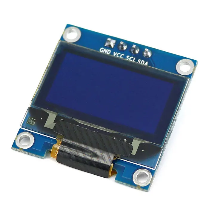
0.96'' I2C OLED Display

Image result for mpu 6050
Accelerometer/gyro sensor(MPU 6050).

Image result for mlx90614
Temp Sensor (MLX 90614). Fancy stuff.
It can tell the temperature of an object right infront of it, as well as the ambient temp.

Image result for arduino pulsesensor
Pulse sensor.(We ditched this sensor mid way.)
Image result for arduino relay module
Relay module.

Image result for ds3231
DS3231 RTC module.


Image result for adafruit powerboost 1000c
Adafruit Powerboost 1000C
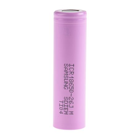
Image result for 18650
18650 liion battery
Image result for bluno nano
Bluno Nano.
Arduino Nano w/ intergrated bluetooth module.


Image result for arduino nano
Arduino Nano.
Image result for rpi 3
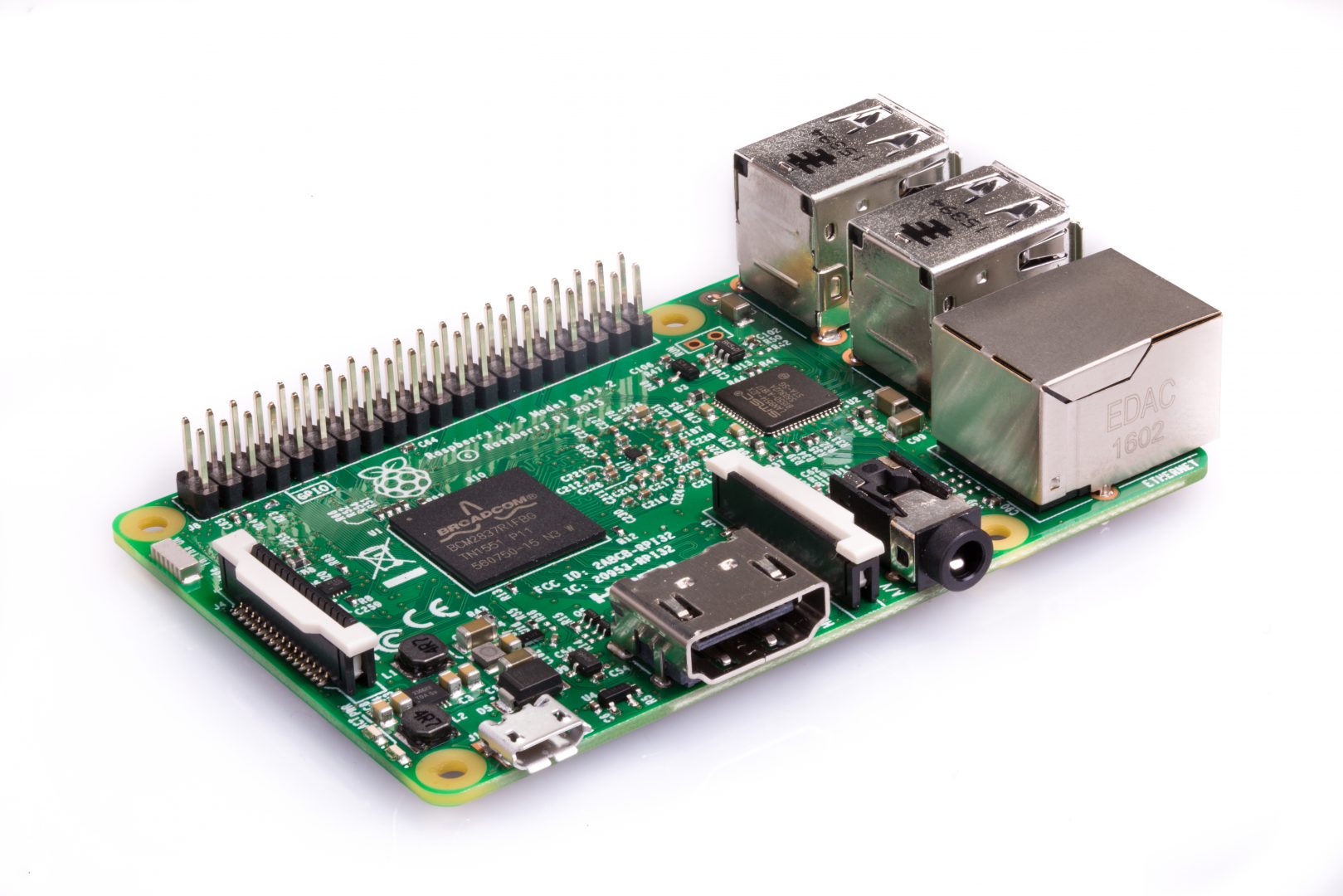
Raspberry Pi 3 Model B.


+ random wires, resistors, capacitors, buttons,servo motors + metal brackets, EVA foam, glue, knives, tape, heatshrink tubing, solder, soldering iron, heatgun, lighter, cables, chargers, more shit.

MK.I

This thing. Like...WTF?
This thing was just a piece of shit. It was shoddy, shitty, didn't have a battery or a screen, didn't have a pulse sensor, was made out of paper.... None of the wires were soldered, it was JUST for testing. didn't last a day. but we DID get data from that thing. MK.I was nothing more than a proof of concept, checking the software stuff more than the hardware stuff. And it served as a base for MK.II, which lasted Way longer, and was way more comfortable. 


MK.II

Finally, Something wearable. It has a screen, a knob to change what was displayed on the screen, SOLDERED WIRES, comfy,spongey materials, more integrity, and...just...all around better. It still had a LONG way to go. Still wired(Both battery wise and data transfer wise), no lock mechanism, was made out of a foam sponge and electrical tape. even with all these flaws, we still managed to get some data. 


Mk.III

MK.III. This one uses an arduino uno. It also has a LCD shield instead of the OLED screen. The straps are made of EVA foam, and...electrical tape. electrical tape FTW. This one didn't work that well. The code was sorta..all over the place. the sensors dodn't work well with the LCD,.... many problems.


Ditching Sensors


Look at these numbers. LOOK AT THE FUCKING GRAPH! JUST FUCKING LOOK AT IT! The thing's all over the place. The number ranges from 25 to 236. That's not human. Similar shit happened with the temperature sensor. Human peoples aren't supposed heat over 40 degrees Celsius. After multiple tries, and multiple failures, (and by multiple, I mean a shit ton) we decided to ditch the pulse sensor.


MK.IV

Kay. MK.IV. The final thingy. We decided to ditch the pulse sensor, and replace it with an accelerometer. We also switched the arduino nano we were using to a snazzy thingy called a bluno nano, which has a integrated bluetooth module in there. Wireless data transfer was a go.
The code DID get a LOT dirtier. 
Well. we made the thing out of EVA foam. it was a lot comfier. a lot sturdier. a lot better. We even added a battery. Velcro locking mechanism. Unfortunately, I don't have any solo photos of MK.IV. but I do have a photo of all the devices together. Looks cool in my opinion.(Mabye that's because I'm the one who took it.)
BOOM.

The pink Pip-Boy like thing is the MK.IV. Looks cool,eh? It came a long way from the first one.


Raspberry Pi Stuff

Okay. to be honest, The raspberry pi part wasn't my part. I don't know much of the details. I suck at python.  The code receives the data transmitted from the armband thing. it calculates if the dude is sleeping via the accelerometer values, and chucks out a HIGH/LOW signal to a connected Arduino. It also chucks out a txt file. Cool shit, eh?  My friend who wrote this code is a wizard.


Controlling Appliances

We used relay modules for this job. It's probably a terrible idea, since this method just cuts the power to the appliances, but I don't give a shit. Anyways, We cut open an extension cord, soldered on a 5v adapter, and connected a relay module. 

We also made a switch-turning-off robot with a servo motor. What...Like....why....who.....
anyways, it kinda worked.

these are connected to a arduino which is connected (via USB) to a raspberry pi.

This thing. the pot is there for testing. it came off later.


Code And Shit


This is the schematic for the armband. 


Look at it. Take time to take it all in. Noice.


The code and stuff are here: https://github.com/flthtmtlf/2017STEAMRnE_HomeAutomation/tree/beta


Tuesday 14 November 2017

Fallout 4 inspired, Working Gauss Rifle (coilgun) -- Part 3

The Capacitors, Part II (A.K.A. The unhealthy charging circuit)

I have 3 capacitor banks. Each bank has 6 capacitors. All of them connected in parallel. I used a XL6009 DC-DC boost converter that ramps up 5 volts to 55 volts. (Output is adjustable.) Mine was laying around so I just used it. There are probably WAY safer ways to charge the caps, but I don't give a shit. This thing's probably gonna end up on a shelf anyways. 
Anyway, I got a 1K Ohm resistor, and connected it parallel to the caps and the output of the boost converter.

Screw Everything.
yep. I'll also probably add a relay or transistor or something to control the charge via arduino.

Aesthetic Parts - "Capacitor Boosting Coils"

The In-Game Gauss Rifle (With the "Capacitor boosting coil" mod/upgrade)  has 4 coils on the side.I have no idea how these would boost the coils. My best guess is that they act as air coil inductors for a "booster" circuit. Anyways, My coils are going to be there for just looks. I designed a coil-spool-holder-thingy in Fusion360, and 3D printed it. 

The 4 U shaped pieces  are printed separately and slid into the main holder.

Half-Assed Assembly

After the parts were done printing, (I used grey PLA from an unknown cheap brand) I got excited and didn't take any photos. So here's a photo of the thing now. Starting to take shape. Awww Yesss


Thursday 2 November 2017

Fallout 4 inspired, Working Gauss Rifle (coilgun) -- Part 2

The Arduino Case

Now, for the grip and arduino case. Going to 3D print this too. I drew that in Fusion 360. the thinner box glues to the previously made capacitor/baseplate mix. An Arduino sits in the other box, and the box slides in the top thingamajig. I'll probably have another locking mechanism, but for now, i'll just print that.
Box on the left is the "lid". Arduino sits in the right box.
Hopefully nothing goes wrong. 

The Capacitors

I had some 25v, 6800uF capacitors left from a previous project(And by "some", i mean a shit ton.), and i originally was going to use them. But nah. I ordered some 63v, 2200uF capacitors. (I needed them for a school project anyways).  
The energy stored in a capacitor is calculated by this formula:

W = 1/2 C V^2  


W = Energy stored (In Joules/J)

C = Capacitance (In Farads/F)

V = Voltage (In Volts/V)

Using this formula, we can calculate that each capacitor would be able to hold up to about 4.3 Joules. But, I am a little pussy, and I'm not going to charge the capacitors up to their max ratings of 63 volts.  I'll probably charge them up to like, I dunno. 50~55? I guess. 55v. That drops the energy stored into about 3.3 Joules. Whatever. I have 18 of those.

The Coils


I wrapped the coils around some random pieces of tubing I had lying around. I used 1mm thick enamel-coated copper wire.(Also known as magnet wire or speaker wire) I wrapped each coil about 200 times. By hand. 3 of them. What am I doing with my life.

200 Times each. What am I doing with my life.
Light gate sensors go in the holes.The white material is what I call "Macgyverglass' ,which is a cheap, poor man's alternative for fiberglass made out of toilet paper and superglue. It's there to reinforce the tubing.

Saturday 28 October 2017

Fallout 4 inspired, Working Gauss Rifle (coilgun) -- Part 1

Yes, I know that the game is old, but I like it. I also don't give a shit. So, I'm going to build a coilgun that does it's best to look like the thing from the game.

The Gauss Rifle from Fallout 4 (The Art of Fallout4)

General Ideas and Stuff

Looking at the gun, it has 6 capacitors on each side(With the full capacitors mod), and has 5~6 coils. I'm guessing that it's a 6-stage coilgun, with 2 capacitors per coil. I don't have the skills, time, money, or patience to make a 6-stage coilgun. so I'm just going to make it a 3-stage coilgun.


Some basic plans I drew in MS Paint
because my laptop(With Photoshop) broke and i was too lazy to install photoshop on my desktop


The capacitors go on the side, just like in the game.
I'll probably control the firing with MOSFETs, and control those MOSFETs with an Arduino. those will be shoved in the foregrip of the gun, along with extra capacitors.
The capacitor charging circuits will be in the "box-thing with the nixie tube displays". I'll probably have a 7-segment display to show stuff instead of the nixie tubes in-game.
The batteries will be held in the cylindrical-tube thing along with the charger.
About the magazine... I have no idea. The gun will probably end up as a muzzle-loader so...

Designing the Capacitor and Coil Holders


I drew the thing up in Fusion 360 to 3D print. Since I have a small buildplate, I'll have to cut them up. I'll print 12 capacitor holders and 12 base plates. The capacitor holders have holes for the leads, and the baseplate has grooves for the wires. In the in-game model, each capacitor has 2 holder-ring-thingies. Fuck that. I'm Just gonna have one holder-ring thingy. Because I hate support material. I HATE grinding and sanding the burrs and leftover support materials. 

Capacitor holder. capacitor goes in the round thingy. Leads go through the holes.

Baseplate. Glue this under the capacitor holder. Wires go in the trenches

Preview of the Thingies assembled. The coil assembly goes in the big groove in the middle.


4:3 Screen. Deal with it.
Now just gotta 3D print that shit. And wrap coils while waiting.